LED Pressure plate dice
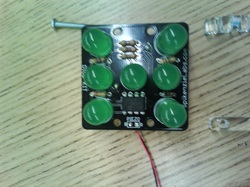
The first day of the electrical engineering program we made LED pressure plate dice. When you press down on the Printed Circuit Board (PCB) the pressure plate (Piezo sensor) causes the LEDs to randomly light up and show a number between 1-6. The signal sent from the sensor, is read by the PIC chip which converts the analog information into a decimal value, which is used to obtain a random result between 1-6. The LEDs are connected to the PIC chip through a series of resistors. The instant the dice kit is struck, the Piezo sends a pulse that immediately wakes up the PIC chip and starts running the program.
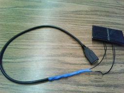
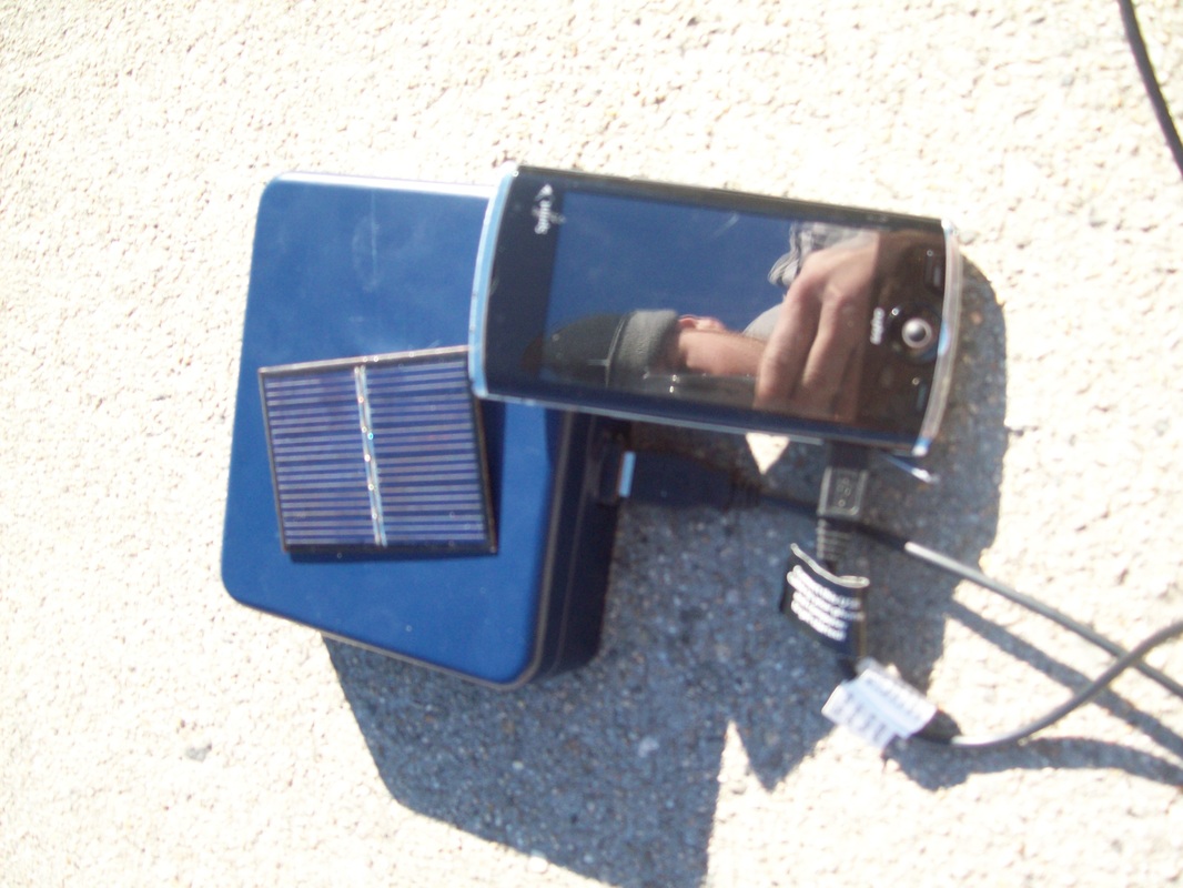
Solar powered phone charger
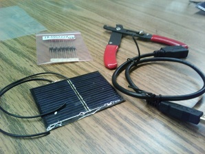
The second week of the engineering program, we made a solar powered phone charger using a few over the counter items found at Radioshack. All you need is a USB extension cable, a solar cell, a 5.1v Zener diode, a rectifier diode, and a solder iron. The first step is to cut the male end of the USB cable. We had to cut away the cables outer insulation, and splice the (red and black) power lines. We then had to solder the rectifier diode between the red wires from the solar cell to the USB cable. This eliminates incorrect polarities and prevents power from being drained from USB devices. Then we connected the black wires together. We then had to solder the Zener diode across the two wire connections. After connecting all the components we used heat shrink tube to protect the connections. Later that night I decided to make housing for the solar panel and USB jack. I ended up using a metal container that my wallet came in when I purchased it.
The Noisy Pencil
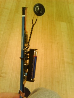
Drawdio is an electronic pencil that lets you make music while you draw. It is a simple music synthesizer that uses the conductive properties of pencil graphite to create different sounds. The PCB consists of 2 resistors, 3 capacitors, a speaker, a TLC551 chip, and a AAA battery. The first thing we learned through this project was about the power supply. The power source comes from a single AAA battery that is encased in a plastic container. There is a switch designed on the PCB which can connect or disconnect the battery from the rest of the circuit. There is also a large electrolytic capacitor, that is used as a bypass capacitor. This is used to smooth out any ripples that is caused by power surges. The heart of the circuit is the TLC551 chip. This is an integrated circuit that is designed for creating timers and oscillators. The frequency of the oscillation is set by 2 resistors and a capacitor. The chip slowly feeds current into the capacitor until it is full and then slowly drains it out. The resistors set how fast to fill and drain the capacitor. The size of the capacitor also indicates how long it takes before it fills. This system is pretty much identical to a Japanese water fountain, except its all with electrons instead of water, and the capacitor is the bucket. The electrons can oscillate at thousands of Hertz, which means it can make audible sound (human hearing can range between 20Hz to 20000Hz). The circuit contains an open connection: two tabs at the end of the PCB. Instead of using a resistor between the tabs, we used the conductivity of the human body and graphite instead. The human body has a resistance similar to a 200,000 ohm resistor. Graphite has resistance of about 1 ohm per square inch, when in the form of pencil lead. When its spread out on a piece of paper, the resistance goes up a lot, creating different sounds. The resistance creates an audio frequency. This frequency is not powerful enough to play through a speaker though. We used a Class B push-pull amplifier, which uses two separate transistors to amplify the sound.
Orange powered alarm clock
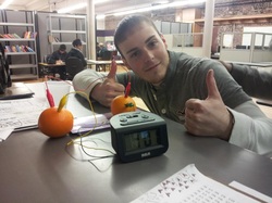
Orange-powered clocks work by using the process of electrolysis. The orange juice is an acidic electrolyte, which is then connected in a circuit through a metal electrode. There must be two different metals present to produce an electric charge; zinc and copper (I used a paper clip and a penny). Otherwise, an outside electric source would have to be present to induce electrolysis. The two metals produce the current necessary to charge the electrolytes, thus allowing the process of electrolysis (separation) to occur and electricity to flow enough to power a clock.
Electrolysis: the passage of an electric current through an electrolyte with subsequent migration of positively and negatively charged ions to the negative and positive electrodes.
Electrolysis: the passage of an electric current through an electrolyte with subsequent migration of positively and negatively charged ions to the negative and positive electrodes.
